FEATURES
- 26 GHz to 115 GHz Models
- Up To 40 dB Isolation
- < 100 nsecs Switching Speed
- Integrated TTL Drives
Specifications
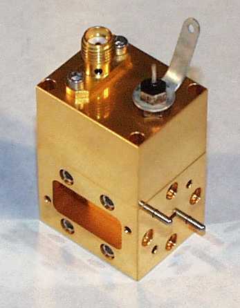
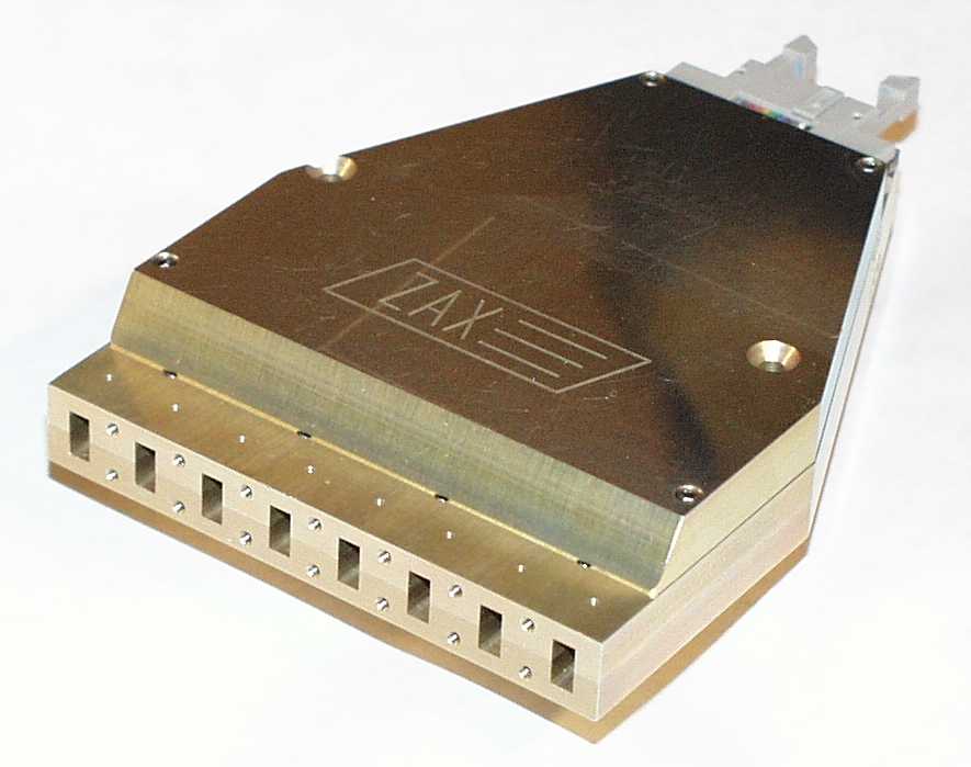
RF Waveguide Model Number
Designation
Q WR-22 33-50 383/U ZPIN 22/xx-xx/xx/xx U WR-19 40-60 385/Um ZPIN 19/xx-xx/xx/xx V WR-15 50-75 385/U ZPIN 15/xx-xx/xx/xx E WR-12 60-90 387/U ZPIN 12/xx-xx/xx/xx W WR-10 75-110 387/Um ZPIN 10/xx-xx/xx/xx F WR-8 90-140 387/Um ZPIN 8/xx-xx/xx/xx D WR-6 110-170 387/Um ZPIN 6.5/xx-xx/xx/xx G WR-5 140-220 387/Um ZPIN 5/xx-xx/xx/xx
Options Available:
- integrated TTL driver
- multi-throw, SP2T, SP4T, SP8T.....
- custom units
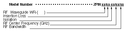
Ordering Information
Also specify the following: Flange pattern ( if non standard ) Example: To order an SPST PIN Switch with a minimum isolation of 20 dB and an insertion loss maximum of 2 dB over a 92 to 94 GHz frequency range, a WR-10 waveguide, and a standard UG-387/Um flange pattern,
specify a ZPIN 10/2-20/93/2.
Subject to change without notice.